
In order to detect the gravitational waves from astronomical events, gravitational wave detectors must be capable of unambiguously measuring displacements of the order of \(10^{-18}\) m/√Hz or less. As the residual seismic motion of the earth can be a trillion times larger than this, significant care must be taken to isolate the measurement optics from such disturbances.
The ambitious goals of the AEI 10 m Prototype impose similarly strict limits on the motion of the measurement optics. As in all current (and planned) full-scale interferometric detectors, the optics will be suspended as the final stages of multiple-stage cascaded pendulums, where the natural frequency filtering effects of resonant pendulum systems are used to isolate the optics from seismic motions at frequencies above the pendulum resonances.
Filtering out motion from the ground
Let us consider a suspension system to be any which exhibits simple harmonic motion, for example a mass on a spring or a mass on a pendulum. The filtering effect can be seen by looking at the transmissibility of these system, which defines how much motion the suspended mass will experience when the suspension point (i.e. the other end of the pendulum or spring) moves. This can be derived from Newton’s equations of motion.
When the suspension point moves in a sinusoidal motion with very low frequency, then the suspended mass will simply follow this motion and no filtering of motion takes place. If the frequency of the motion of the suspension point increases, then eventually it will hit the natural frequency of the system where the system resonates. At and around this resonance frequency, the suspension point motion is actually amplified by the system. At frequencies above the resonance frequency, the transmissibility starts to decrease with higher frequencies with a \(1/f^{2}\) dependence. Therefore it is only at high frequencies (above the resonance frequency) that a suspension is able to filter out motion, with better filtering performance at higher frequencies.
An animation demonstrating a transmissible plot for a suspended pendulum is shown below.
The amplified motion due to the resonance can reduced by introducing damping to the system by extracting energy from the system. Depending on the type of damping used, this could result in poorer isolation performance above the resonance frequency, as is the case for eddy current damping.
Two main types of suspensions are used for our optics. Vertical isolation is provided by suspending mass from blade springs, while horizontal isolation is provided by pendulum suspensions. These are cascaded into multi-stage suspensions to give the desired isolation performance. Each stage adds an extra resonance frequency but also provides an additional \(1/f^{2}\) of isolation at high frequencies. Our “triple” suspensions typically have three pendulum stages and two blade spring stages to provide \(1/f^{6}\) isolation in horizontal and \(1/f^{4}\) isolation in vertical motion.
In addition to individual optic suspensions, a “pre-isolation” stage is formed by the optical tables themselves. Additional stability will be provided by a Suspension Platform Interferometer (SPI) controlling the relative motions and orientations of the tables.
Suspension Systems in the AEI 10 m Prototype
An interferometer is a complicated system, where the noise and suspension requirements for each optic have to be tailored to their individual purpose. Broadly, there will be three classes of suspension required for the first stage of experiments in the prototype: 100 g triple-stage suspensions for the main interfereomter mirrors, larger mass triple-stage suspensions for other critical optics, and auxillary single-stage suspensions.
100 g triple suspensions
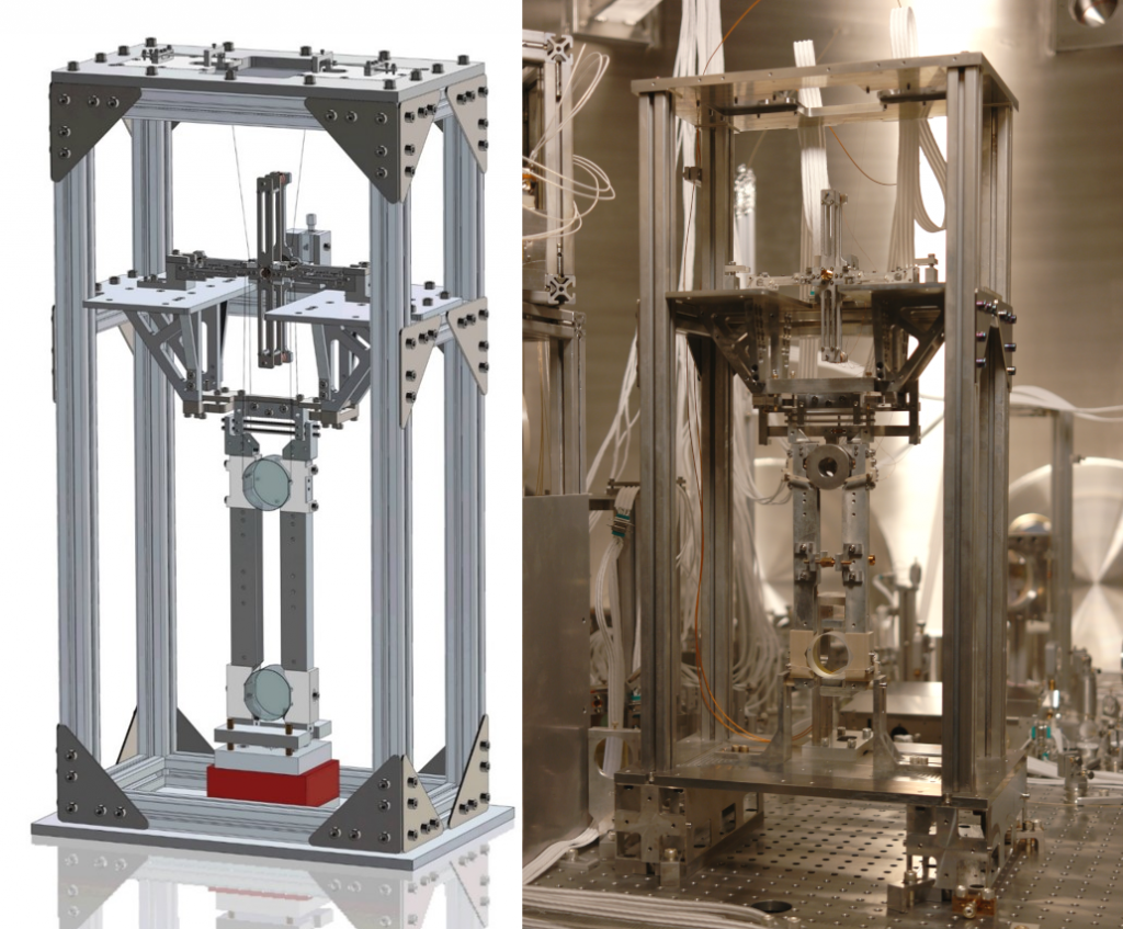
Right: Photo of a 100 g triple suspension installed in the vacuum system with pilot optic suspended with wires
To reach the goal of SQL limited measurements, high laser power and low mirror masses are required. A mirror mass of 100 g should allow this goal to be reached while still allowing a practical – though challenging – suspension design to be realised. As it is the motion of these 100 g mirror which we are inevitably trying to measure with our sub-SQL interferometer, these are arguably the most critical suspensions in the AEI 10m Prototype.
The design and manufacturing of these suspensions were done in close collaboration with our colleagues at the Institute for Gravitational Research at the University of Glasgow (as are many of our suspensions). In order to sufficiently isolate the optics, a triple-stage suspension (with two stages of vertical isolation) will be needed.
Thermal fluctuation of the suspension ‘wires’ due to the environment having a finite temperature (room temperature) causes the mirrors to shake. The relative length of the two arms of the interferometer therefore fluctuates randomly, which is directly measured by the interferometer. This is called suspensions thermal noise. This noise can be reduced by using a material with low mechanical loss, as it also reduces the amount of coupling from thermal to mechanical energy, as dictated by the fluctuation-dissipation theorem.
The final pendulum stage of the 100 g test mass mirrors comprises a monolithic fused-silica structure with the test mass mirror suspended using 20 µm diameter fused-silica fibres to reduce thermal noise. Very similar suspensions were used in the Sagnac Speedmeter project at the University of Glasgow.
Cleaving module
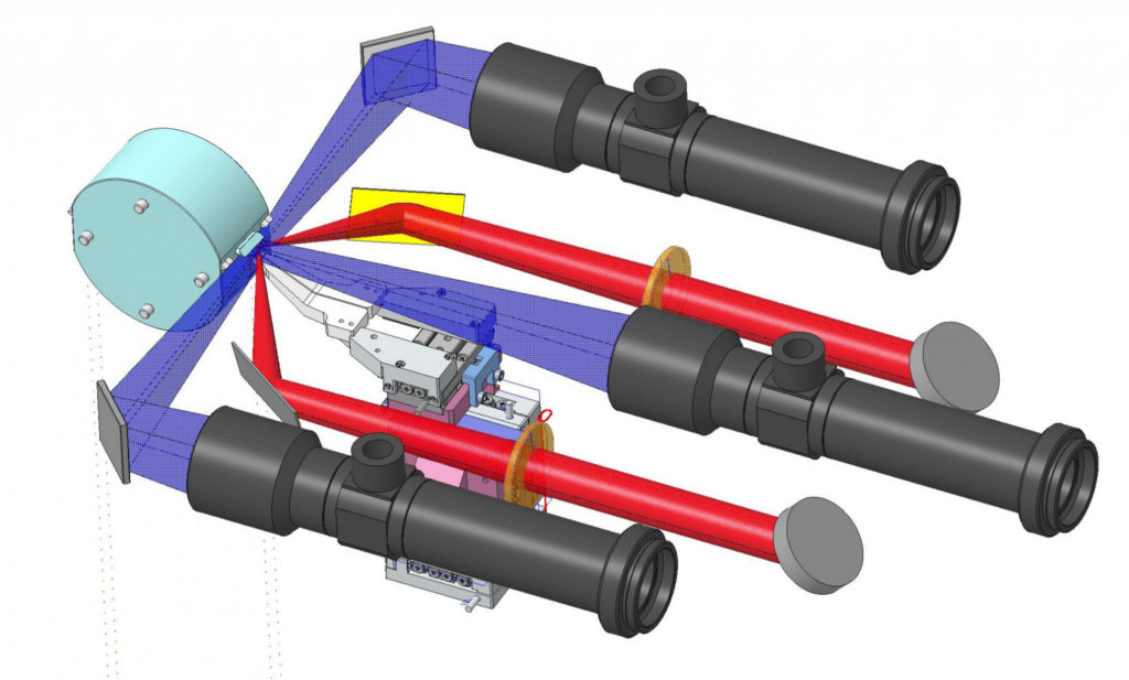
The glass fibres will be welded to the masses with a CO2 laser. The welding spots of two fibers are only separated by 4.5 mm from each other. To avoid an excessive pitch of the suspended mirror, micrometer precision is required for the welding process. With the Fraunhofer Institute for Applied Optics and Precision Engineering (IOF), we are developing an precision welding system. With the setup, we will characterise the fibres, laser cleave them and automatically weld the last pendulum stage. A 120 W CO2 laser laser can be either directed to a cleaving module or a welding jig.
To achieve equal tension in all four fibres of the final suspension, they are cut to a specific length. In the cleaving module, a CO2 laser line is set to a fixed cut position. The fibre is mounted in a cartridge. A slip stick piezo fibre gripper aligns the fibre in x- and y-direction After the first cleave, a z-stage drives the opposite fibre end to the cleave position with 1 μm precision. The process is monitored with a camera in 180° to the CO2 laser beam.
For welding, 60 W laser power are sufficient. A beam splitter switches between the welding spots at the top and bottom. A 120° opening angle of the CO2 laser beams heats the fiber homogeneously. Three cameras are used for alignment and monitoring.
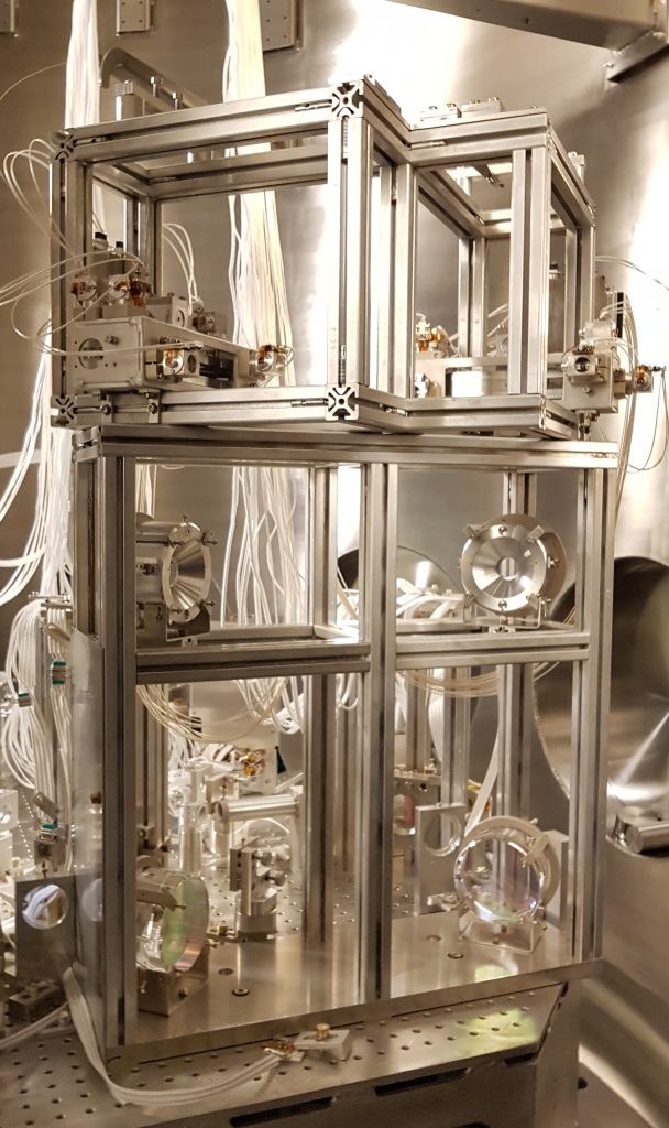
850 g triple suspensions
The frequency reference cavity will use 850 g mirrors. This was chosen as a compromise between minimising the effect of radiation pressure noise and having compact suspensions. Similar to the 100 g triple suspensions, these are made up of three pendulum stages and two blade spring stages. However, the mirror will be suspended from an aluminum intermediate mass using 50 µm steel wires (it will not be monolithic fibre stage). This is sufficient to keep the vertical lower stage resonance to around 20 Hz and first “violin” mode of the wire to above 400 Hz, hence keeping features out of the desired measurement band of the sub-SQL interferometer.
The same suspension design is also used for the AEI 10m Prototype Thermal Noise Interferometer
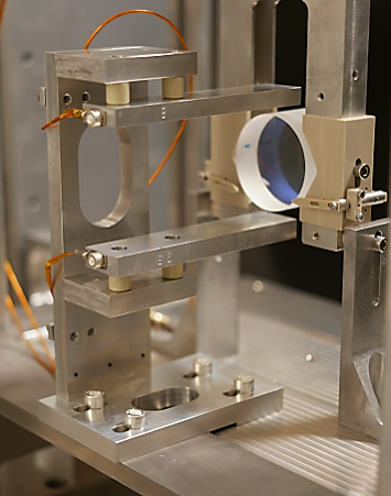
Beam splitter suspension
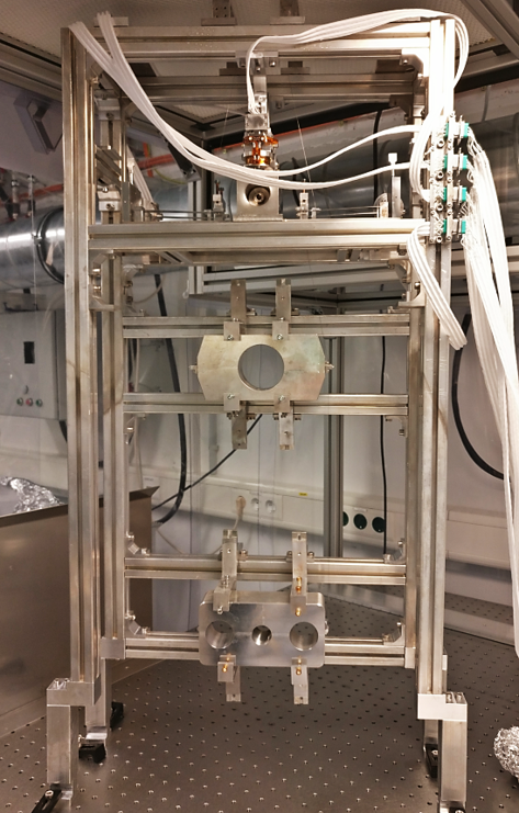
The sub-SQL interferometer beam splitter will also be suspended as a triple suspension with three horizontal and two vertical stages. The planned rectangular shape for the beam splitter is unique for gravitational wave detectors, but was necessary for the sub-SQL interferometer due to mass and space constraints. The mass of the beam splitter will be 1.5 kg. The photo shows a suspended dummy aluminum mass to test the performance of the suspension while waiting for delivery of the actual beam splitter.
Ancillary Optics
Other optics are required to steer and point the laser beam into and out of the main interferometer and the vacuum system. Due to the excellent isolation and stability provided by the isolated optical tables the SPI system, such ancillary optics can be isolated with relatively simple single stage suspensions systems, with no additional vertical isolation stages.

How are the suspended optics controlled?
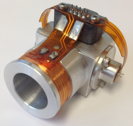
Coil/Magnet actuators
All of our suspensions are equipped with coil/magnet actuators. Small magnets are attached to one of the suspended masses, and wire wound coils are attached to the suspension frame, with a magnet positioned just in front of it. An electrical current passing through the coil generates a magnetic field, which generates a force on the mass to which the magnet is attached to. This allows us to move the suspended mirror from outside the system even when the system is under vacuum.
It is desirable to places coil/magnet actuators as high as possible on the suspension chain. This is because noise will inevitably couple to the magnet, for example electronics noise in the coil circuit or stray magnetic fields in the vacuum system. By placing the coil/magnets high on the suspensions chain, this noise can be filtered out by the lower suspension stages.
Optical levers
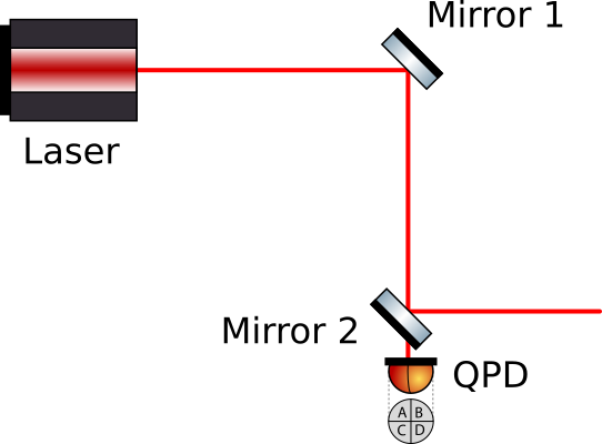
One way to determine the angular alignment of a mirror is to measure the position of the laser beam after reflection. This is done by installing a quadrant photodiode (QPD) behind the next mirror in the beam path. Although the mirrors are high reflectivity (most reflect >99.99% of the light), the small amount of transmitted beam can be measured. The QPD measures the position of the beam by comparing the amount of light on each quadrant. The position of the beam on the QPD will be determined mostly by the angle of the previous mirror.
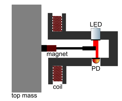
BOSEMs
The 850 g and the 1.5 kg beam splitter triple suspensions are equipped with BOSEMs (Birmingham Optical Sensor and Electro-Magnetic actuator) at the top stage. These are a combined motion sensors and actuators. The sensor is comprised of an LED light source and a photodetector. A “flag” is attached to the upper mass which blocks half of the LED light on the photodiode in the aligned state of the suspension. As the mass moves, the flag blocks more or less light on the photodiode allowing the relative position between the BOSEM and the mass to be read out. Actuation is achieved by passing current through a co-located coil on the BOSEM which acts on a magnet attached to the mass.
The BOSEMs are useful for aligning the position of the mirror from outside the vacuum system. In addition, they can be used to actively damp the suspension, in particular reducing the motion at the suspension resonance frequencies. The advantage over eddy current damping is the ability to specifically target damping of the resonances and avoid sacrificing isolation performance at higher frequencies within the detection band.
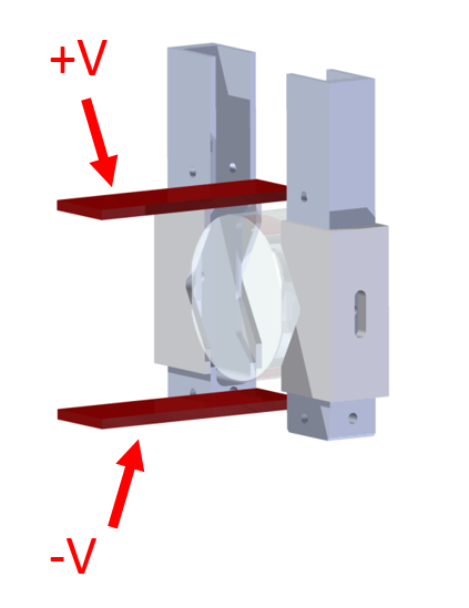
Electrostatic drive (ESD)
The test mass mirrors requires a fast actuator in order to acquire and hold interferometer lock (keeping the interferometer at its operation point). Additionally, this needs to be as low noise as possible to not ruin the sensitivity of the interferometer. This is achieved by using an electrostatic drive. A strong electric field is generated near the fused-silica mirror. As the mirror is a dielectric, it is attracted to where the electric field is stronger.
This is implemented for the 100 g test mass mirrors using a parallel plate design. This is installed such that the mirror is near the edge of the parallel plates where the electric field is non-uniform. A voltage difference up to 500 V is applied across the plates to actuate the motion of the 100 g mirror.
A design like this is not possible for full scale gravitational wave detectors due to the very large mirrors, which would require extremely high voltages. Alternative ESD designs are used instead.