
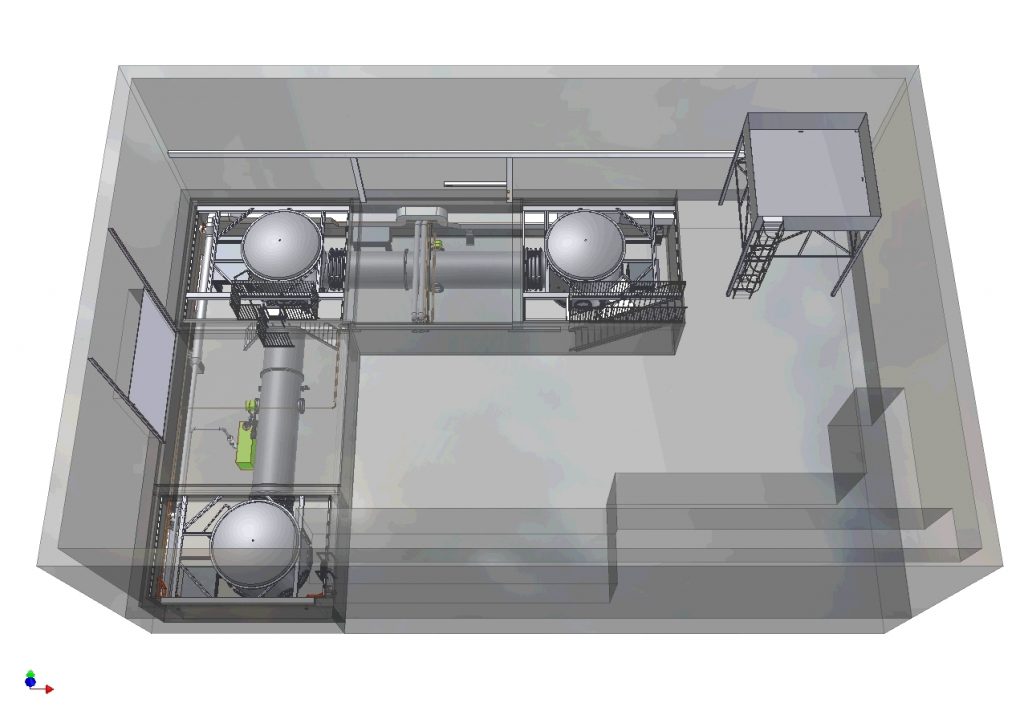
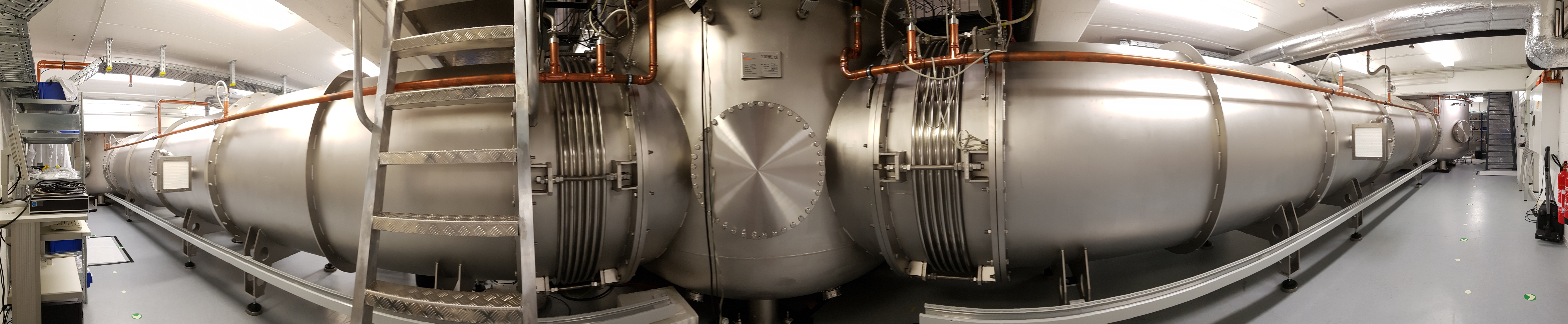
The vacuum system for the AEI 10m Prototype consists of three tanks with a diameter of 3 m and a height of 3.4 m, which are connected by 1.5 m diameter tubes. The tubes are segmented for ease of installation and made of about 22 t of stainless steel. Overall, the vacuum system encloses a volume of approx. 100 m3.
The vacuum system is actually located in the downstairs area of the 10 m Prototype laboratory, while the upstairs area is used as lab space for auxiliary systems (such as the SPI setup) and for assembly of mechanical parts (such as the suspension systems).
Why do we need a vacuum system?
Operating the interferometer under vacuum serves three main purposes:
Acoustic shielding: Vibrations in the air (i.e. sound waves) couple directly into the interferometer by pushing on the suspended optics. Acoustic fluctuations are nearly inevitable in a laboratory, e.g. from air conditioning, people, computers etc. A vacuum envelope prevents vibrations from reaching the suspended optics via the air.
Refractive index variations and scattering: As light propagates along the arms of the interferometer, it will also interact with the air molecules in its path. The optical path length difference between the two arms can fluctuate due to differences in the non-stationary air molecules in the two arms. This interaction is minimized as the volume of air molecules is minimised by the vacuum.
Cleanliness: Keeping the experiment under vacuum also helps ensure that there are no dust particles in the experiment. Not only does dust change the optical path of light which interacts with it via scattering, but it can be particularly damaging for optics as the high intensity laser beams can cause it burnt into the optic!
Pumping the system down
There are no gate valves for sectioning the vacuum system and therefore it is only possible to vent the whole system. A powerful roughing pump is attached to the west tube. It is a screw pump which pumps 170 L/s, starting from atmospheric pressure. Once a pressure of less than a millibar is reached two magnetically levitated turbo-molecular pumps are started. Each of them has a pumping rate of 2000 L/s. The two turbo-molecular pumps are supported by a single scroll pump. With this pumping system, a residual pressure of the order 10-6 mbar is reached within 12 hours. After one week of pumping, a pressure below 10-6 mbar remains. It is dominated by water vapour as the system will not be baked. However, longer pumping will further reduce the residual pressure.
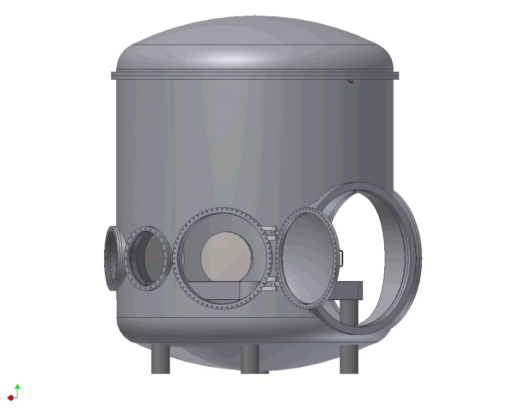
Several flanges are available on each tank. These are used for:
- cable feedthroughs to electrically connect various sensors and actuators from the outside
- optical fibre feedthroughs to send laser light into the vacuum system
- viewports to allow beams to travel out of the vacuum system and to look inside with cameras.
All flanges up to 600 mm diameter are sealed with copper gaskets. Since we are a prototyping facility, we want to regularly go into the vacuum system in order to make changes. The doors are not sealed with gaskets but rather by two Viton O-rings each. The gap in between these O-rings is pumped by another scroll pump. The interconnects between the arms tubes are also sealed this way. This scheme of differential pumping allows us to reach very low residual gas pressure while keeping the cost for the vacuum system at a tolerable level.
The scroll pumps for backing and differential pumping of the big flanges are located in a pump room separated from the lab. They are set up on a double stack vibration isolator made of two granite plates (about 200 kg each) and two layers of Sorbothane hemispheres. The pumps themselves also stand on Sorbothane dampers.
The vacuum system was fully installed in February 2009. The remaining leaks at the interconnections of the tube segments were sealed off in May 2009 by the insertion of slightly thicker O-rings.