Juliane von Wrangel defends PhD
Congratulations to Juliane von Wrangel for completing her PhD!
Juliane’s thesis, “Micrometer Precision Bonding and Laser Welding of 100 g Suspensions for the AEI 10m Prototype”, tackled the challenges of preparing the 100 g quasi-monolithic suspensions for the Sub-SQL Interferometer. These, due to their small size, have different challenges compared to the large test mass mirrors found in full-scale gravitational wave detectors. The highlights from the thesis was the use of cold plasma treatment to clean the tiny fused silica parts in preparation for hydroxide catalysis bonding and the development of a new CO2 laser welding machine in collaboration with the Fraunhofer Institute for Applied Optics and Precision Engineering IOF and the Institute for Gravitational Research, University of Glasgow. Juliane’s work marks an important step toward realising the Sub-SQL Interferometer!

Going beyond standard quantum limit with an optical spring
Author: Artem Basalaev
At the 10 m Prototype, several technologies will be used to reach incredible displacement sensitivity of the main interferometer. Our 100 g test masses will be coated with AlGaAs coatings and suspended by the thin silica wires from seismically-isolated optical tables. This setup will allow us to reach the Standard Quantum Limit (SQL) in sensitivity: the lower limit on the combination of the quantum radiation pressure noise (QRPN) and shot noise (SN) at each frequency, as dictated by the Heisenberg uncertainty principle. Achieving this level of sensitivity is necessary to create an environment that resembles current and planned future gravitational wave detectors to subsequently test new technology for them.
One focus is on developing technologies that allow us to surpass the SQL, that can be used in future detectors. One such technique is squeezing (injection of a squeezed vacuum state). This introduces a cross-correlation between QRPN and SN which reduces total achievable quantum noise. This technique has been successfully applied at current detectors, especially at LIGO, where the frequency-dependent squeezing has been perfected [Ganapathy et al 2023]. Frequency-dependent squeezing requires a high-finesse, low-loss, long-length filter cavity. At LIGO, the filter cavity is 300 meters long. At future Einstein Telescope (ET) detector, the filter cavity will have to be an incredible 5 km long to achieve 15 dB of squeezing in the low-frequency interferometer [Korobko 2025]. Needless to say, building such a long filter cavity with the required low loss and high finesse is extremely technically challenging.
Fortunately, there is another complementary technique that will help us surpass the SQL threshold for ET: the so-called optical spring [Corbitt 2007]. ET’s signal recycling cavity will be detuned from its resonant condition, introducing two distinct minima in the sensitivity spectrum: one corresponding to the optical resonance of the detuned signal recycling cavity, and another corresponding to the opto-mechanical resonance of the optical spring. Carefully chosen detuning ensures the highest sensitivity at low frequencies up to around 20 Hz. At higher frequencies the high-frequency interferometer of ET will take over.
The optical spring amplifies the amplitude of the classical output signal at the optical spring frequency, while leaving the output quantum fluctuation unaffected. Therefore, it can and will be combined with frequency-dependent squeezing to maximize benefit. However the two-minima structure of the sensitivity, created by the optical spring, requires not one but two 5-km-long filter cavities for squeezing! Nevertheless, the benefits of the optical spring are expected to outweigh the challenges. Therefore the two-filter-cavity, optical spring, combined with frequency-dependent squeezing, is currently the envisioned configuration for the low-frequency interferometer of ET [Korobko 2025].
Unlike frequency-dependent squeezing, the optical spring has not yet been tested for shaping sensitivity beyond the SQL at the current gravitational wave detectors. Therefore it is a good candidate to test first at the 10 m Prototype to ensure the success of the future gravitational wave detectors, particularly ET.
Optical spring: how it works

Creating an optical spring, for a signal-recycled Fabry-Perot Michelson interferometer, can be described as follows:
- The signal recycling cavity is detuned from the resonance condition by moving the signal recycling mirror → affecting position of the input test masses and therefore the the field amplitude in the arm cavities.
- The position of the arm cavity mirrors is also influenced by the radiation pressure force ← which depends on the field amplitude in the cavity.
- This creates an opto-mechanical feedback mechanism that acts similarly as if the mirrors were connected by a mechanical spring (or an anti-spring).
- At the optical spring frequency the sensitivity of the interferometer is resonantly enhanced. This effect is independent of the SQL, meaning that the SQL can be surpassed!
Optical spring at the 10 m Prototype
In a signal-recycled Fabry-Perot Michelson interferometer, an optical spring is created by moving the signal recycling cavity mirror. However, signal recycling is not planned for the 10 m Prototype. Nevertheless, all necessary conditions to introduce an optical spring will be met. Sub-SQL interferometer will reach the SQL in the range of approximately 65 Hz to 200 Hz, making it a good test case for real gravitational wave detectors. Moreover, unlike squeezing techniques, which shape the noise, the optical spring effect, which shapes the signal response, actually does not rely on being limited by the SQL.
Rather than using a signal recycling cavity, the optical spring will be introduced directly in the arm cavities by moving the end test masses, modifying the common arm (CARM) degree of freedom, defined in the schematic above. We will use our electrostatic drives (ESDs) to add detuning to the arm cavities by moving the end test masses. Typically, ESDs would keep the end test masses positioned such that the arm cavities are in a resonant condition. Here, however, we will use them to introduce a static offset of a few nanometers. This offset must be the same in both arms; otherwise, it will also change the DARM degree of freedom, which is undesirable because we will monitor the change in sensitivity there.
A study with Finesse 3
A study using realistic parameters for optics, geometry and the test mass suspensions model of the 10 m Prototype has been conducted with Finesse 3. The study was performed in two variations:
- One used 5 W of main laser power (the default configuration foreseen at the 10 m Prototype). The end test masses were moved by up to 4 nm, corresponding to detunings between -0.10 and -3.00 line widths of the arm cavity, with a step of 0.25 line widths.
- The second used 50 W of main laser power (which would be possible if power recycling is introduced at the 10 m Prototype). In this case, the end test masses were moved by up to 9 nm, corresponding to detunings between -0.25 to -6.50 line widths of the arm cavity, with a step of 0.10 line widths.
The points of maximum sensitivity from this sweep measurement were connected, to create an optical spring sensitivity limit. The result is shown in the figure below.

The study’s conclusion is that, with the anticipated 5 W of laser power, the optical spring’s improvement should be detectable at various detunings in CARM. For 50 W of laser power, the improvement is more significant but requires larger detunings. The complete simulation, together with the exact parameters of the 10 m Prototype and its suspensions is available in the attached Jupyter notebook.
From the Finesse 3 study to implementation
An attractive property of the optical spring experiment at the 10 m Prototype, is that it does not require any additional changes to the planned Fabry-Perot Michelson interferometer. The detuning in CARM will be achieved using the ESDs that will be installed for controlling the test masses. Monitoring will be performed in the DARM degree of freedom. There’s no conflict with any other planned experiments, that can be set up in parallel. The other experiments will only be affected during the short measurement time when the end test masses are actively moved. The optical spring effect is also robust against unwanted disturbances. Unlike techniques manipulating quantum noise, it can be observed even when classical noise sources dominate. Lastly, even a fully functional Fabry-Perot Michelson interferometer is not required. Initial studies can be conducted with a single cavity.
An important factor for successfully quantifying the impact of the optical spring is precise calibration of the detuning. It is important to move the end test masses to the same detunings, thereby changing the CARM degree of freedom. Any mismatch will also introduce a DARM offset. From the variations of the parameters in the Finesse 3 study linked above, it was found that the optical spring can tolerate a small DARM offset. However, an unknown offset will complicate the interpretation of the results.
To calibrate the ESDs, a photon calibrator (PCAL) will be used. A PCAL is a laser that applies precisely known radiation pressure to the mirror. The produced force can be compared to the ESD and therefore used to calibrate it. To calibrate the PCAL itself, an integrating sphere can be used. An integrating sphere precisely measures laser power by capturing nearly all laser light, which is then detected by a photodiode. The photodiode measurement is precisely calibrated by the manufacturer, with calibration traceable to a NIST or PTB standard.
Calibration should also be monitored to compensate for possible drifts during the measurement by the means of injecting additional calibration lines. Both ESDs will be excited at around 500 Hz and monitored in DARM. Any difference in the observed amplitudes of the lines in DARM will therefore indicate miscalibration and will be corrected by adjusting the ESD gains. At lower frequencies, below 10 Hz, another set of two lines can be injected with the ESDs. At these frequencies, the actuation is mostly done by the coils on penultimate mass (PUM, the second suspension stage), which fully compensates for the induced low-frequency motion of the test masses. Therefore, the difference is that, for low frequencies, the calibration lines should be monitored in the PUM actuation signals instead of using DARM directly. Having these four calibration lines present ensures stability of the calibration.
Surfing the (gravitational) waves: dynamical signal tracking
As the study above showed, changing the cavity’s detuning shifts the optical spring frequency. Gravitational wave signals from inspiraling compact binaries follow a characteristic “chirp” pattern. As they progress toward merger, they rapidly rise in amplitude and frequency. Can we change the tuning on the fly, to maintain detector’s maximum sensitivity as the signal progresses? As if surfing gravitational waves? The answer is yes! However several challenges must be taken into account for such dynamical signal tracking.
First, feasible optical spring frequencies in a gravitational wave detector like ET tend to be at the lower end of the detection range, below a few hundred Hz. It may be possible to overcome this limitation by using more complex setups, such as utilizing multiple optical springs [Rehbein et al 2008]. However, it is more feasible to first focus on the advantages that an optical spring can offer in terms of low-frequency sensitivity.
Second, while the (static) optical spring is in the baseline of the ET low-frequency interferometer, there are additional challenges arise from dynamic changes in tuning. These challenges relate to controlling the interferometer and interpreting the results.
All current and planned gravitational wave detectors rely on linear control theory to operate. However, a Fabry-Perot Michelson interferometer is fundamentally a nonlinear system, where changes in power depend strongly, and nonlinearly, on the mirrors’ detuning. The trick that allows this to work is that, in the operational state, changes to the mirror positions are so small that changes in power considered linear. A linear controller is fully capable of maintaining desired positions. However, dynamical detuning to follow a progressing signal may no longer allow this. In fact, a state in which nonlinear dynamics are dominant is observed in current detectors all the time—during alignment and before the detector locks. Currently, this issue is overcome by a process that brings the detector to lock. This process often relies on random motion to bring the mirrors into the desired position by chance and then “catch” them there with a controller. This process is highly specific to each detector and often requires manual intervention. Fortunately, there has been significant progress lately in automated MIMO and nonlinear controls based on neural networks [Qin et al 2024; Ma, Vajente 2024]. A neural network can learn the nonlinear behavior of a system. These networks can be used as both sensors and controllers and can be combined with a Kalman filter to extract the maximum amount of information from limited and noisy inputs.
A second challenge arises from the behavior of noise during dynamical tuning. The noise floor is typically assumed to be stationary during the time that each signal spends in the detector. When this is not the case, we call it “glitches”, that have to be filtered out [Merritt et al 2021]. If this is not possible, the data may have to be discarded. Depending on the exact rate of change, with dynamic tuning, the noise may behave in a significantly non-stationary way. This may necessitate a reevaluation of the approach to data analysis and statistical inference. A changing noise model may need to be incorporated directly into the likelihood function used to infer the source parameters and their confidence intervals. Coincidentally, a similar situation may arise at ET even without dynamical tuning. Since ET will likely observe several signals simultaneously [Baka et al 2025], the other signals will serve as a dynamically changing background for any given signal. Therefore, developing robust inference methods for the dynamic case can generally be useful for future detectors.
It remains to be seen how much the above challenges will limit dynamical tuning for signal tracking. The 10 m Prototype experiment is ideally suited for this study. After setting up the optical spring with static tuning, dynamical tuning can be gradually introduced. A mock signal can be injected with the PCAL, and then recovered in DARM and reconstructed. The rate of tuning can then be increased, and the detector control and noise behavior can be closely monitored. This will allow us to find the threshold at which nonlinearities and nonstationary noise play a significant role and develop algorithms to address them.
If dynamical signal tracking proves reliable, new and exciting possibilities emerge. For example, highly eccentric black hole inspirals will manifest at low frequencies and feature a prominent second harmonic [Romero-Shaw et al 2019]. The optical spring can amplify this second harmonic to further boost confidence in the estimation of parameters of such a source. This would provide strong evidence that black holes coexist in dense environments such that they can encounter each other and merge within a short time, astronomically speaking. Furthermore, if the LISA space-based detector comes online, it will likely observe intermediate-mass black holes. Some of these black holes may transition into the ET observation band within minutes [Jani et al 2020]. This would allow us to anticipate their arrival and start dynamical signal tracking at precisely the right moment.
To fully utilize the potential of future gravitational wave detectors, we may need to rethink how we operate them. To do so, we must test new promising techniques, such as the optical spring and signal tracking with it, using available prototypes and simulations.
DetailsLVK Poster Prize awarded to Matteo Carlassara
Congratulations to our PhD student Matteo Carlassara on winning the best poster at the 2023 September LIGO-Virgo-KAGRA (LVK) meeting held in Toyama, Japan!
His poster “Balanced Homodyne Detection at the AEI 10 m prototype: status update” was selected as the best on an experiment/instrumentation topic among a total of more than 100 posters. It outline the current progress towards implementing a balanced homodyne readout for the Sub-SQL Interferometer at the AEI 10m Prototype, including some of the challenges that Matteo is currently tackling.
DetailsFibre welding machine delivered!
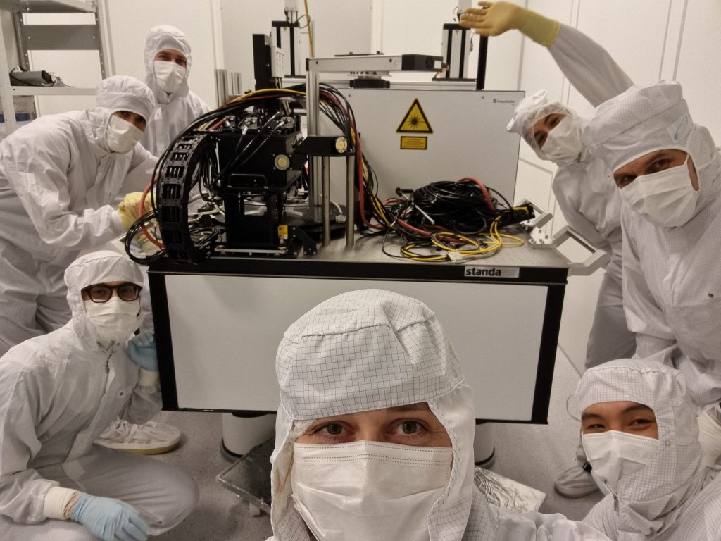
The Sub-SQL Interferometer is a step closer to realisation with the delivery of our fibre welding machine, the output of a collaborative project with the Fraunhofer Institute for Applied Optics and Precision Engineering IOF in Jena and funded by Center of Excellence Quantum Frontiers.
To ensure that the Sub-SQL Interferometer is not limited in sensitivity by suspension thermal noise, it was envisioned that quasi-monolithic suspensions similar to those used in gravitational wave detectors would be used. For the small 100 g optics in the Sub-SQL Interferometer, suspension fibres (“wires”) with diameters of 20 µm are required, thinner than the average human hair! Initial tests by our colleagues at the university of Glasgow found that indeed the technique for larger aLIGO mirrors, using a CO2 laser to weld the fused silica fibre with the fused silica test mass and penultimate mass, could be scaled down but with extremely tight tolerances required to ensure that the suspension can hang without excessive tilt.
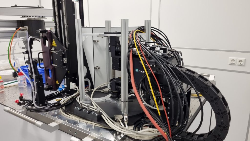
The project with the Fraunhofer IOF was established with the goal of developing a highly accurate, repeatable and automated welding machine to produce our quasi-monolithic suspensions with the ability to easily re-weld existing suspensions for position corrections when required. Juliane von Wrangel led the efforts from the AEI 10m Prototype side to finalise the requirements and designs. The final device uses a CO2 laser with several cameras and precision actuators to control the welding process with custom software and user interface.
The 20 µm fused silica fibres will be provided by our colleagues from the Institute for Gravitational Research at the University of Glasgow.
The machine was recently delivered and installed into our clean room. Fine tuning and further testing will follow and we excitedly await the production of quasi-monolithic suspensions!
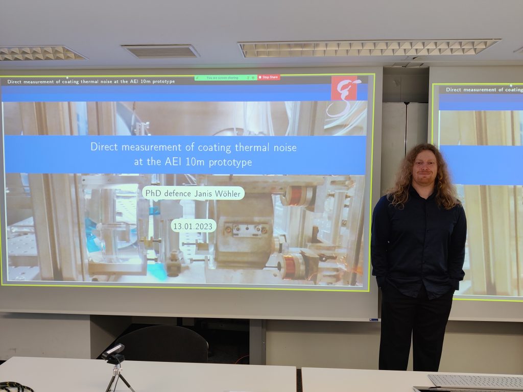
Janis Wöhler defends PhD
Congratulations to Janis Wöhler for completing his PhD! Janis’ thesis was titled “Direct measurement of coating thermal noise at the AEI 10m Prototype” which was centred around work on the thermal noise interferometer (TNI).
Janis was able to bring the noise of the TNI to a level of 1 · 10⁻¹⁸ m/√Hz and successfully measured the coating thermal noise of a high reflectivity silica-tantala (Ta2O5/SiO2) sample mirror. This was the first demonstration of a direct thermal noise measurement in the audio-band in Europe.
Janis will soon be taking up a postdoctoral position at the University of Maastricht.
Sub-SQL beam splitter installed
The core beam splitter for the Sub-SQL Interferometer has been installed into the vacuum system and is now freely hanging in its triple suspension system.
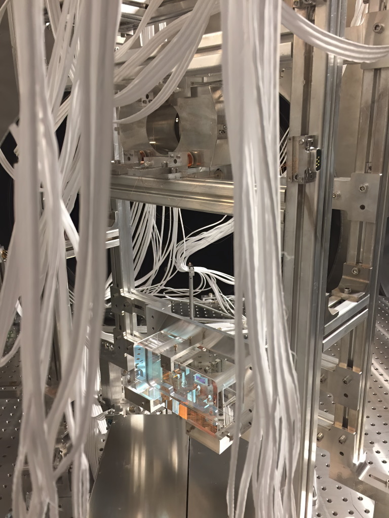
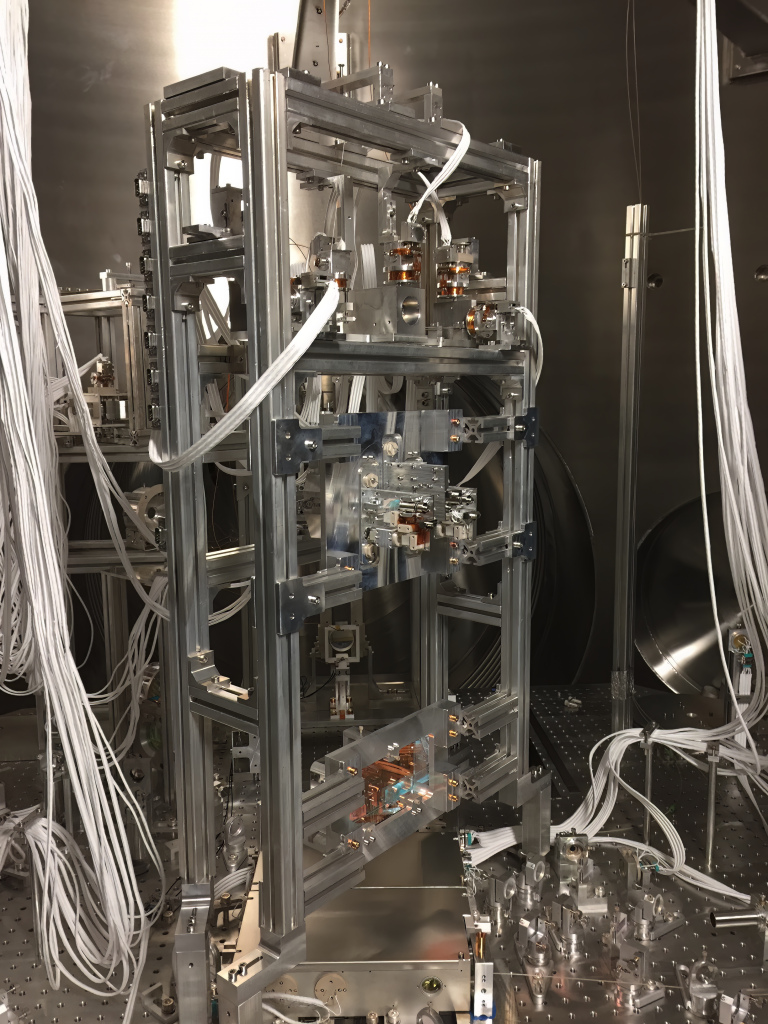

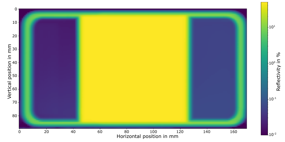
Unlike typical beam splitters used in gravitational wave detectors, the shape of our beam splitter is rectangular rather than round. This is because the beam splitter should be wide enough for secondary internal reflections (ghost beams) to exit the beam splitter through the optical surfaces rather than the barrel of the optic so that those beams can be effectively dumped. A round beam splitter fulfilling this requirement would hit the optical breadboard of the suspension platform interferometer (SPI) located directly underneath. This breadboard is housed in the aluminium box below the beam splitter in the above photos. Additionally, the rectangular shape reduces the mass of the beam splitter by approximately 50% compared to round version. This is critical for reducing the total mass on the optical table, which is limited due to the seismic attenuation system.
The beam splitter side of the optic does not use a uniform coating. Instead it uses a split coating design where only the central part of the surface has a beam splitter coating. The sides are anti-reflection coated to suppress further ghost beams.
More details about the design of the beam splitter and its suspension system are available in chapter 4 of Philip Koch’s PhD thesis.
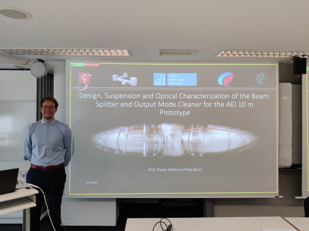
DetailsPhilip Koch defends PhD
Congratulations to Philip Koch for successfully defending his PhD thesis titled “Design, Suspension and Optical Characterization of the Beam Splitter and Output Mode Cleaner for the AEI 10 m Prototype”. Philip’s thesis work covered a range of topics including:
- the thickness homogeneity of crystalline AlGaAs/GaAs high reflectivity coatings
- the design, construction and characterisation of the main sub-SQL Interferometer beam splitter and it’s triple suspension
- building the “scatterometer” – an apparatus to characterise the scattered light produced by optics by measuring the bidirectional reflectivity distribution function (BRDF)
- the design and construction of an outpupt mode cleaner cavity for the sub-SQL interferometer, with a measured intra-cavity loss of < 0.5%
PhD positions in the AEI 10m Prototype
We have openings for talented and highly motivated students to join the AEI 10m Prototype as PhD students to work on bringing the sub-SQL interferometer online and to its design sensitivity. Topics will include the design and installation of suspended optics, interferometer control, scattered light mitigation, and noise identification and suppression.
The closing date for applications is 19.04.2022. More details and application instructions can be found on the AEI home page:
https://www.aei.mpg.de/901369/phd-positions-in-the-aei-10m-prototype
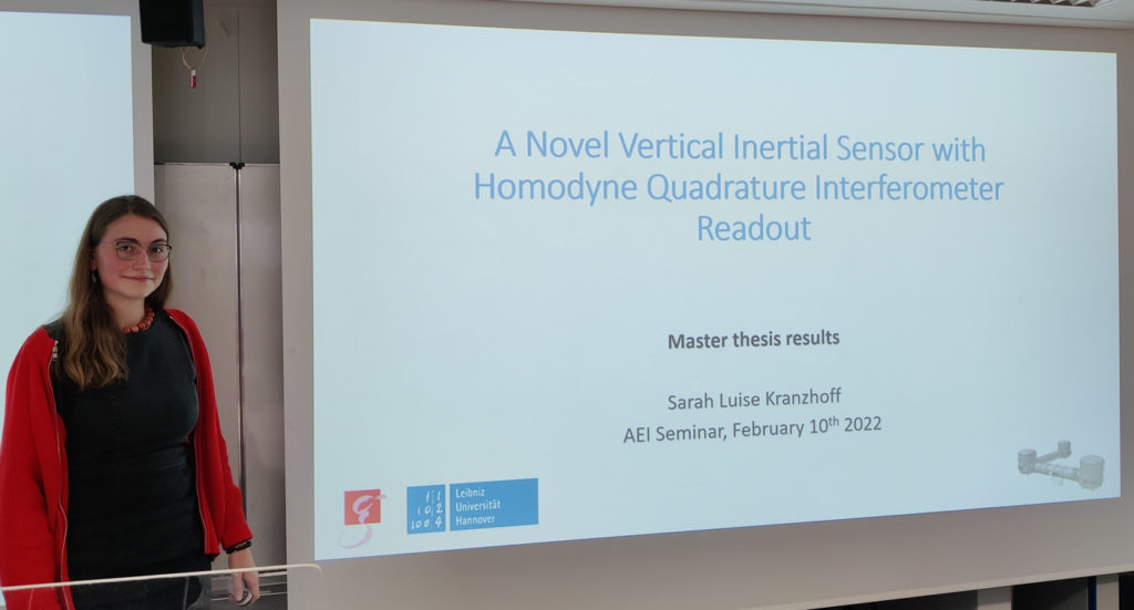
Luise Kranzhoff completes Masters degree
Congratulations to Luise Kranzhoff for successfully completing her masters studies! Her Masters thesis was titled “A Novel Vertical Inertial Sensor with Homodyne Quadrature Interferometer Readout” where she designed and characterised a new sensor and investigated their potential use as part of the AEI-SAS. Her thesis work was done in collaboration with the University of Birmingham and Vrije Universiteit Amsterdam.
Luise will soon start her PhD studies at the University of Maastricht in the Netherlands.
Robin Kirchhoff defends his PhD
Robin Kirchhoff will receive his PhD after successfully defending his PhD thesis titled “Implementation of an active seismic isolation system for the AEI 10 m Prototype”. Robin’s work was centred around the implementation of active control schemes to seismically isolate the pre-isolation platforms in the 10 m Prototype and how they can be optimised to suppress noise in the Sub-SQL Interferometer.
Congratulations Robin!