Why is the SPI needed?
The three optical tables inside the vacuum system are all well isolated from ground motion via the seismic attenuation systems (AEI-SAS). The AEI-SAS ensures good seismic isolation at frequencies significantly higher than the fundamental resonance frequencies of the AEI-SAS. However, at lower frequencies the tables are more prone to differential drifts in position. This is due to slight difference between the tables due to the mechanical tolerances from the manufacturing and assembling processes. Thermal effects and very low frequency seismic activity are therefore coupling differently into each table.
The suspension platform interferometer (SPI) is used to compensate for this by measuring the relative motion between the tables. This signal can then be used in a feedback loop to keep the differential distances of the tables locked by using the voice-coil actuators equipped on the tables. A longitudinal displacement noise between two tables below 100 pm/√Hz at 10 mHz has been demonstrated using the SPI.
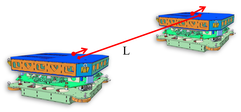
The SPI only controls the differential motion between the tables as it is this type of motion which is detrimental for the sub-SQL interferometer. This is because differential motion directly changes the arm lengths of the Michelson interferometer and hence directly contributes noise. In contrast, the sub-SQL interferometer is not sensitive to common motion of the tables, whereby the tables all move by the same amount in the same direction, since the arm lengths do not change. The three AEI-SAS therefore behave as a single platform by moving together.
How does the SPI work?
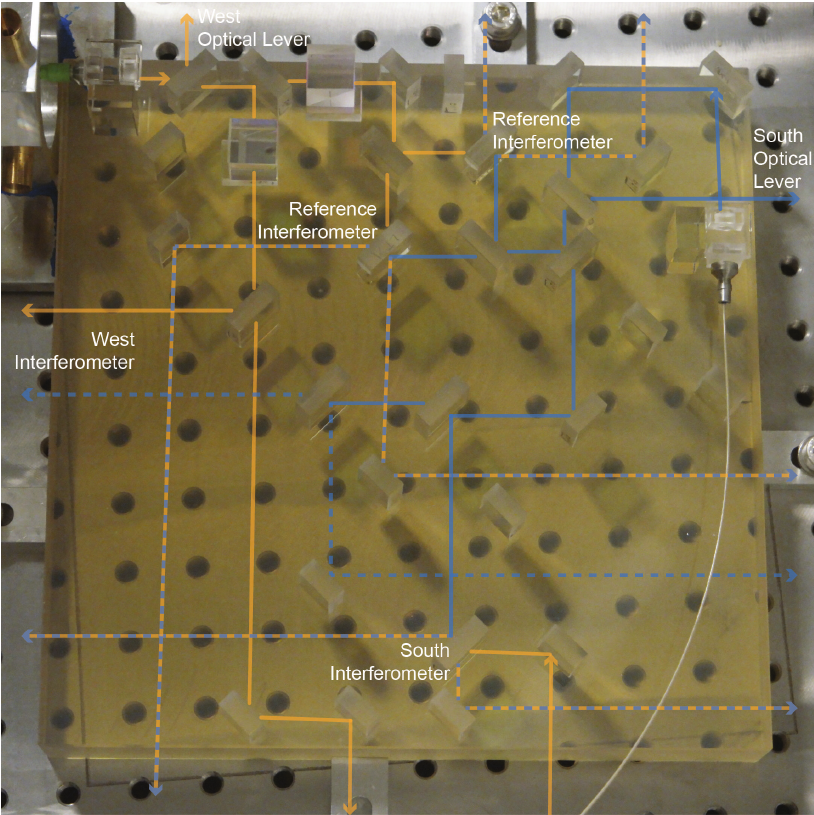
The SPI actually consists of two separate interferometers to measure the central-to-south table distance, and the central-to-west table distance. These are configured as Heterodyne Mach-Zehnder interferometers.
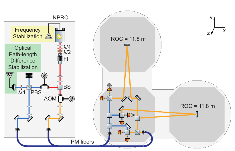
The measurement interferometers measures the distance between two tables by comparing the phase between two laser beams. One of these beams is sent from the central table to the other table and reflected back to the central table. The reference beam stays on the central table and is combined with the measurement beam using a beam splitter. Photodidoes are used to measure the interference between these two beams.
In addition to the measurement interferometers, there are also two reference interferometers. These directly measure the heterodyne beat signal without sensing the other table. These reference interferometers are required to measure relative phase fluctuations acquired by the two beams from the laser preparation bench and through the optical fibres.
These interferometers are in a heterodyne configuration, meaning that the two beams being interfered have a frequency difference of 15.34 kHz (the heterodyne frequency). This is achieved by frequency shifting the two beams coupled into the vacuum system by using acousto-optic modulators (AOMs) with a frequency difference equal to the heterodyne freqeuncy. The heterodyne signal measured by the photodiodes is a 15.34 kHz beat signal plus phase shifts induced by relative table motion with respect to the reference arm of the interferometer.
Low noise, high sensitivity of the SPI at low frequencies is achieved by having a very stable reference arm of the Mach-Zehnder interferometer. This is achieved in the SPI by using a quasi-monolithic optical layout on the central table. The base plate for the central optics is made from an ultra-low thermal expansion material, Clearceram-Z HS. The optical components, such as mirrors and beam splitters, are made of fused silica. These components are bonded to the base plate using hydroxide-silicate bonding. These optics and the base plate form a quasi-monolithic structure with low thermal noise and drift.
The phase of the heterodyne beat signal is measured using phasemeter. A modified version of the phasemeter developed for LISA Pathfinder is used to extract digitised readout signals for the table displacements. These can be used as error signals for feedback control using our Control and Data System (CDS).
Performance of the SPI
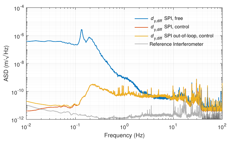
The initial target of the SPI was to control the relative motion between the tables to 100 pm/√Hz at a frequency of 10 mHz. This target was exceeded by an order of magnitude as demonstrated in the PhD thesis of S.M. Köhlenbeck.
Amplitude spectral density (ASD) of the differential longitudinal displacement between the central and south AEI-SAS. The blue plot shows the differential displacement with each table controlled using local sensors. The red and yellow plots show the differential displacement when the tables are controlled using the SPI. The grey plot shows the SPI reference interferometer, which gives an indication of readout noise.
References
K. Dahl, ‘From design to operation: a suspension platform interferometer for the AEI 10 m prototype’, PhD thesis, Gottfried Wilhelm Leibniz Universität, Hannover, (2013). DOI: https://doi.org/10.15488/8033
S.M. Köhlenbeck, ‘Towards the SQL interferometer length stabilization at the AEI 10 m-prototype’, PhD thesis, Gottfried Wilhelm Leibniz Universität, Hannover, (2018). DOI: https://doi.org/10.15488/3567
G. Heinzel et al.,‘ The LTP interferometer and phasemeter’, Classical and Quantum Gravity, 21(5), pp.581–587, (2004) . DOI: https://doi.org/10.1088/0264-9381/21/5/029