The AEI 10 m Prototype utilises many sensors to be read out and actuators to be controlled. For this purpose (digitising and collecting the data of the sensors, controlling the interferometer) we use the CDS (control and data system) software developed by our colleagues at the LIGO sites. The CDS is also used as data acquisition system for the science data and to collect data from ancillary systems like environmental monitoring devices such as room temperature, humidity, and particle counts. The CDS provides access to all the recorded data collected with a time-stamp accuracy of approximately 1 µs for later analysis. The CDS also has a responsibility to protect the interferometers by avoiding damage from hazardous control signals.

CDS Hardware
The AEI 10 m Prototype uses at least 500 channels forming multiple-input multiple-output control loops. Digital-to-analog conversion (DAC) and analog-to-digital conversion (ADC) are performed using 16 bit fully differential PC expansion cards with either PCI-X or PCIe bus connection with the sampling frequency set to 64 kS/s. The frontend server machines are standard Xeon based servers.
As all controlling and data acquisition has to be performed in real-time, special care has to be taken to choose low-latency hardware. Standard gigabit ethernet can only be used for tasks that are not time-critical because of the possibly high latency involved. For low-latency communication we use fibre-based Myrinet connections.
CDS Software
The CDS software is based on a real-time enabled Linux operating system. For the operators control screens and channel access are realised with the experimental physics and industrial control system (EPICS).
The workflow for a digital control circuit involves designing the circuit with the aid of Matlab/Simulink tools, creating a real-time kernel module from this circuit model, loading the module on a real-time enabled frontend computer and controlling the module via EPICS control channels and screens.
Flow diagram
The figure below provides a flow chart of signals going in and out of the CDS.
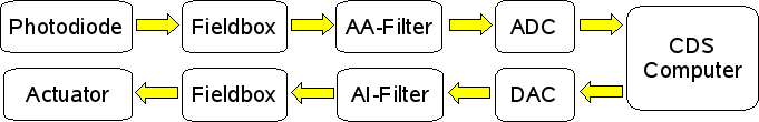
A sensor (photodiode in the example flow chart) generates an analogue electronic signal which we wish to control, for example by measuring the length of a cavity.
The signal is pre-processed using a fieldbox which could includes amplification, filtering or summing with other signals. In particular we apply a technique known as whitening, which maximises the dynamic range of the CDS by amplifying the usually low amplitude high frequency signals.
An anti-aliasing (AA-) filter is used to remove high frequency signals that could produce artefacts in the following analogue-to-digital converter (ADC) due to the discrete sampling.
After the analogue signal is converted to a digital signal, it is sent to the CDS where it is recorded, and further processed. This may include de-whitening the signal by attenuating the high frequency components of the signal to recover the original relative spectrum. Additionally, the digital signal can be calibrated into tangible units, e.g. the mirror displacement in units of \(m\). When the signal is an error signal used for control, a feedback signal is generated by implementing a digital servo. For example, the length error signal from the photodiode is read and converted into a feedback signal to push a mirror with a certain force to correct the error using some actuator. A major benefit of digital processing with the CDS is that feedback loops can be changed on-the-fly with software without the need to modify any hardware.
An actuator signal (or feedback signal) follows a similar path to reading a signal but in reverse. The CDS can output a digital signal, which can be whitened to maximise dynamic range.
This is converted into an analogue signal using a digital-to-analogue converter (DAC), which is subsequently low-pass filtered with an anti-aliasing (AI-) filter to remove high frequency artefacts from the conversion process.
Finally, the differential analogue signal is conditioned (e.g. de-whitening) for the actuator using a fieldbox. The signal is sent to the actuator to exerts the according feedback, e.g. a coil-magnet actuator to push on a suspended mirror to control its position.
CDS Timing
To achieve the desired timing accuracy of about 1 µs for the data acquisition time-stamping we use a custom timing system. This is based on a 2²² Hz master clock phase-locked to a GPS 1 Hz clock. The timing information is distributed via fibres to all real-time enabled data collection units.
References
R. Bork et al., ‘AdvLigo CDS Design Overview’, T0900612-v2, LIGO technical note, (2010) https://dcc.ligo.org/LIGO-T0900612/public