The laser is an essential component of an interferometer. For the Sub-SQL interferometer, an input power of up to 10 W will be used in order to be limited by both quantum radiation pressure noise and quantum shot noise. Additionally, there are also stringent requirements on the laser power and frequency noise to ensure they do not limit the sensitivity of the interferometer.

The laser system
The AEI 10m Prototype Interferometer will use a 35W solid-state laser operating at a wavelength of 1064 nm as its light source. This system consists of a seed laser: a 2 W Nd:YAG non-planer ring oscillator (NPRO) laser. This beam from the seed laser passes through four Nd:YVO4 crystals in an amplifier configuration.
After passing the four laser heads the NPRO 2 W 1064 nm beam is amplified to a power level of 35 W. This laser system was pioneered by the AEI high power laser group and is also currently used as the front-end laser in the LIGO observatories, which is subsequently amplified to even higher power (200 W).
Each crystal is pumped by a fiber-coupled laser diode with a nominal power of 45W at a wavelength of 808 nm. Efficient cooling of the laser crystal was realized by wrapping it into a 500 μm thick indium foil and by mounting this assembly in a water-cooled copper block.
The laser bench is located outside of vacuum. A single mode, polarisation maintaining, photonic crystal fibre (PCF) is used to get the laser light inside the vacuum system and towards the interferometer. This PCF has a large mode-area of 12.6 µm which enables up to 10 W of power to be delivered into the vacuum system before the onset of stimulated Brillouin scattering.
The free running laser system has relatively low power and frequency noise in the frequency range of interest (100 – 1000 Hz). However, orders of magnitude of noise suppression was still required to reach the standard quantum limit.
Power stabilisation
The free running relative power noise of the laser is approximately \(4×10^{-6} \) /√Hz. This is suppressed using our intensity stabilisation servo (ISS).
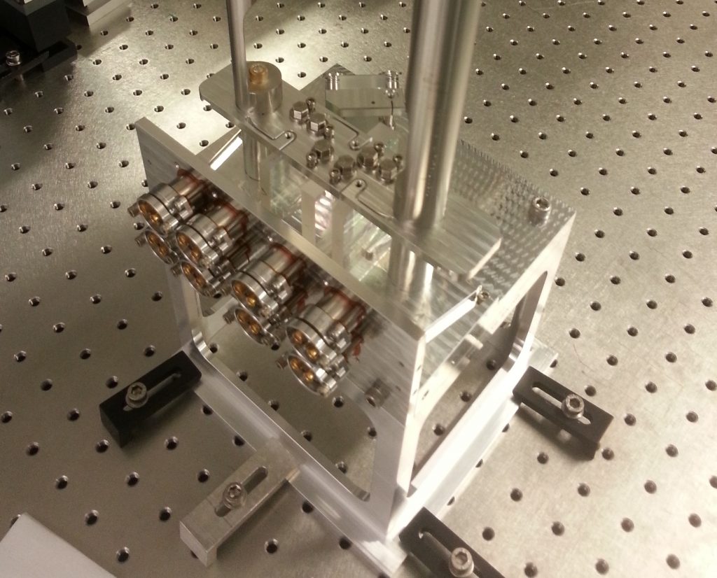
The relative power noise is sensed using an array of four photodiodes installed in the vacuum system. Multiple photodiode arrays are used to split a high power beam into lower power beams which are capable of being detected without damaged to the photodiodes. A fraction of the laser light is picked off before going to the interferometer. The photodiode array senses a total of 150 mW. A feedback loop is used to compensate the measured relative power noise by actuating on the laser power using an acousto-optic modulator (AOM) installed between the NPRO seed laser and the 35 W amplifier. The relative power noise is suppressed by three orders of magnitude to approximately \(2×10^{-9} \) /√Hz, which is the shot noise of the sensed light.
Frequency stabilisation
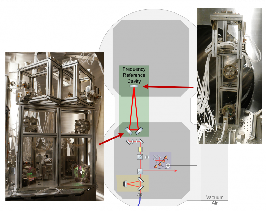
Tight requirements are set for the laser frequency noise to ensure that it does not limit the performance of the interferometer. Frequency noise is suppressed by locking the laser frequency to a dedicated suspended optical resonator in the vacuum system. This is known as the frequency reference cavity. This is a triangular cavity with a round trip length of 21.2 m and finesse of approximately 3500. The relative freqeuncy noise of the locked laser is given by:
\(\frac{\Delta \nu}{\nu} = \frac{\Delta L}{L},\)where \(\nu\) is the laser frequency and \(L\) is the cavity round trip length. It is therefore beneficial to make the cavity as long as possible. The cavity mirrors are suspended as triple pendulums with three horizontal and two vertical stages of isolation to suppress seismic noise. Unlike the sub-SQL interferometer, the mirror mass is relatively large (850 g) to suppress radiation pressure noise. The displacement noise of the reference cavity is given in the figure below.
The laser frequency is locked to the frequency reference cavity using the Pound-Drever-Hall locking technique. A feedback loop is made using three different actuators for different frequency ranges:
- The temperature of the laser crystal for slow, low frequency (< 1 Hz) feedback.
- A piezoelectric transducer (PZT) acting on the laser crystal for intermediate frequencies (1 Hz – 10 kHz)
- An electro-optic modulator (EOM) between the NPRO and the amplifier stage for high frequency feedback (10 kHz – 300 kHz)
A high gain servo is used to suppress the free running laser noise of approximately \(100 \) Hz/√Hz to \(1×10^{-5} \) Hz/√Hz at a frequency of 100 Hz.
Mode Cleaner
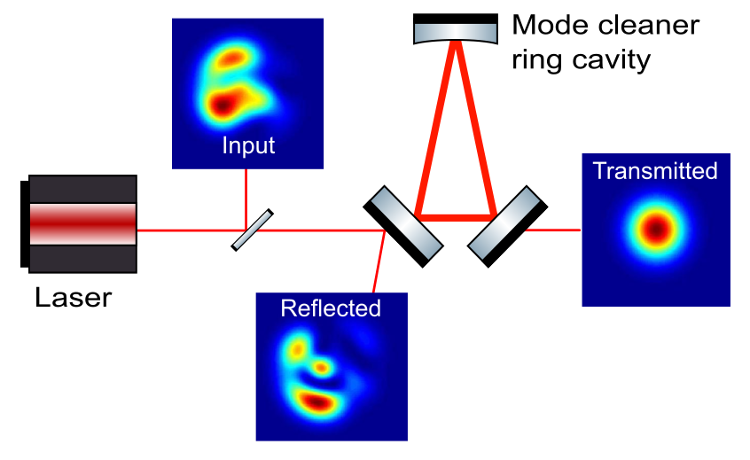
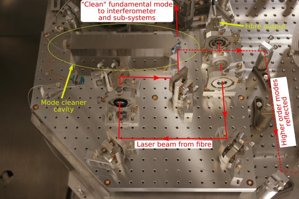
All the optical cavities used in the AEI 10 m Prototype are designed to be resonant for the fundamental Gaussian \( TEM_{00}\) mode. Even small amounts of higher order mode content can significantly lower the sensitivity of the sub-SQL interferometer, as light in these modes are not used to sense the test mass displacement but still contribute readout noise. A mode cleaner cavity is used as a mode filter to separate out higher order modes after coupling the light into the vacuum system via the photonic crystal fibre. This works by only allowing the \( TEM_{00}\) mode to be resonant in the cavity, and hence only that mode is transmitted through. The higher order modes are reflected by the cavity.
The mode cleaner cavity is made of three mirrors in a triangular configuration. Unlike other cavities used by the AEI 10 m Prototype, the mode cleaner mirrors are not suspended, but instead are mounted onto a fixed rigid spacer with a round trip length of 0.53 m. The spacer is made from Super Invar, an alloy with low thermal expansion and is hollowed out to allow the laser beam to propagate inside. The end mirror of the triangular cavity is attached to a long-range PZT, which is used as an actuator to lock the cavity to the laser frequency.
The mode cleaner also provides a stable beam in terms of beam position and angle. This is because beam position and angle flucuations (also known as beam jitter) can also be described as a beam with \( TEM_{00}\) profile being contaminated with \( TEM_{01}\) and \( TEM_{10}\) modes. The mode cleaner therefore provides a stable, constant reference beam to which the sub-SQL interferometer and other sub-systems can be aligned to.
References
T. Westphal, ‘A Coating Thermal Noise Interferometer for the AEI 10 m Prototype facility’, PhD thesis, Gottfried Wilhelm Leibniz Universität, Hannover, (2016). https://doi.org/10.15488/8896
P. Oppermann, ‘Characterization and stabilization of a high power fiber amplifier laser’, PhD thesis, Gottfried Wilhelm Leibniz Universität, Hannover, (2017). DOI: https://doi.org/10.15488/9034
J. Junker et al., ‘Shot-noise-limited laser power stabilization for the AEI 10 m Prototype interferometer’, Optics Letters, 42(4), pp.755-758, (2017) DOI: https://doi.org/10.1364/OL.42.000755
G. Hammond et al., ‘Advanced technologies for future ground-based, laser-interferometric gravitational wave detectors’, Journal of Modern Optics, 61(sup1), pp.S10-S45, (2014), DOI: https://doi.org/10.1080/09500340.2014.920934