What is the Sub-SQL Interferometer?
The sub-SQL interferometer is the interferometer which is housed inside the vacuum system of the AEI 10 m prototype facility. It will be set up to mimic current gravitational wave detectors to provide an interferometer for prototyping gravitational wave detector techniques and technologies. Unlike a gravitational wave detector, which must maintain and maximise observation time, a dedicated prototype facility allows for rapid and regular testing of different technologies and techniques.
Although we are not aiming to measure gravitational waves, we will still measure the position of our mirrors with extremely high precision. A standard Michelson interferometer has a sensitivity limit governed by the Standard Quantum Limit (SQL). We are building our interferometer to be initially limited by the SQL. As the name implies, the sub-SQL interferometer will test techniques to overcome this limit.
What is the SQL?
Unlike a photon or an electron, a macroscopic object is regarded as a classical object. The macroscopic object has been exposed in the messy environment and has lost the quantum property. However, if we can do the measurement with the precision at the level of the SQL, it will recover the quantum property. We will then be able to see the quantum behavior of the macroscopic object and may find out a fundamental difference of the quantum world and the classical world.
Another motivation is the development of so-called quantum non-demolition techniques (QND). The SQL is indeed a limit for a “standard” measurement, however, this is not a fundamental limit. There have been a number of ideas to overcome the limit. Once the sensitivity of the interfereomter reaches the SQL, we can experimentally demonstrate these ideas (hence the name ‘sub-SQL interferometer‘). Successful demonstration of QND techniques will pave the way for them be implemented in full scale gravitational wave detectors to improve their sensitivity. Our facility will therefore play an important role in research and development.
Is it possible to see the SQL?
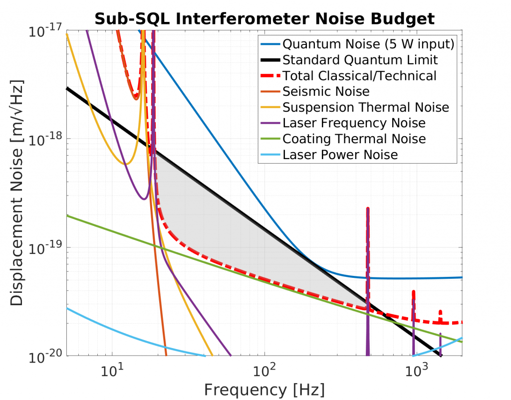
Yes, indeed. A design noise budget is shown in the figure below which shows the dominant noise sources for the sub-SQL interferometer. The dashed red line is the sum of the classical and technical noise sources accounted for in the design of the sub-SQL interferometer. The solid black line shows the SQL with the quantum noise for an example input power of 5 W shown in dark blue.
The shaded region shows the difference between the SQL and the total classical and technical noise in a frequency region between 20 and 500 Hz. We aim to demonstrate QND techniques which can surpass the SQL in this region.
We expect various sources of technical noise to reduce this sub-SQL band which we will not be able to mitigate, for example: imperfect suspensions and stray light in the experiment. We initially target the more feasible goal of being limited by the SQL in the band between 65 and 200 Hz. The lower target of 65 Hz is imposed by internal resonances in our AEI-SAS platforms at lower frequencies, while the upper target of 200 Hz is due to the limited laser power available in the initial configuration.
Current Status
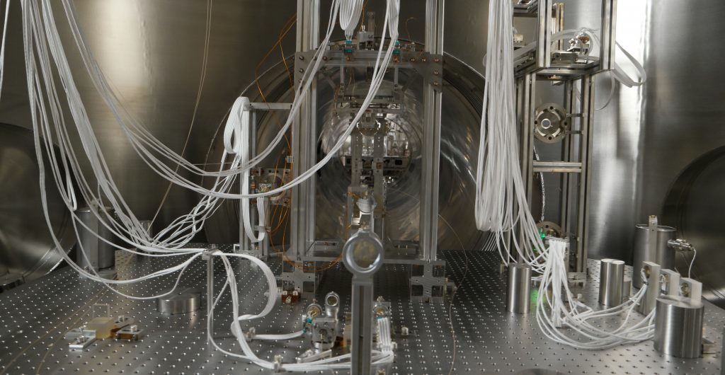
The full interferometer is not yet installed in the vacuum system. We currently have a single arm cavity (the single arm test) installed with pilot optics to test and refine the method of controlling our 100 g suspended optics. The following sub-systems are installed and operational:
- Three seismically isolated platforms (AEI-SAS), controlled with with both local inertial sensors and the suspension platform interferometer
- The pre-stabilised laser system, including power and frequency stabilisation
- The control and data system (CDS)
- A pre-mode cleaner and suspended input mode cleaner
- The beam splitter for the Sub-SQL interferometer
The path towards the sub-SQL interferometer includes:
- Preparing the laser input path to the interferometer using suspended optics
- Preparing the quasi-monolithic suspensions for the 100 g optics and installing into the vacuum system
- Installation of the output mode cleaner
- Installation of suspended optics to couple light into the output mode cleaner
- Implementation of control schemes for the full interferometer
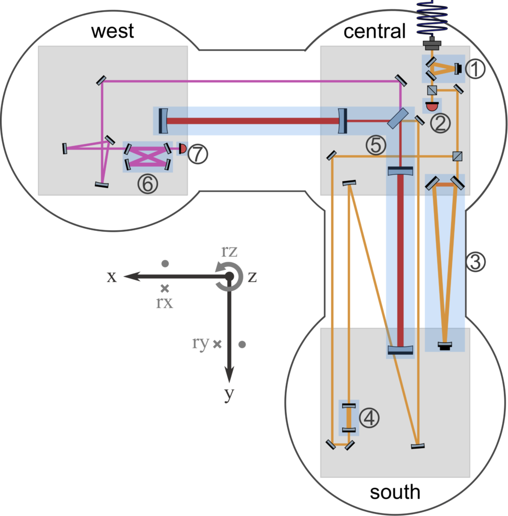
IFOCAD Model of the Interferometer
The video below gives a virtual tour of the inside of the vacuum system showing the envisioned core optical components and laser beam. The model was created by Philip Koch using the IFOCAD software developed by our Interferometery in Space colleagues at the AEI Hannover.